|
||||||||||||||
| Introduction This modification is in two parts. The first is to improve the overall clarity of the SSB audio signal by attenuating the unwanted noises below 300Hz. This is achieved by changing the value of C93. The second is to improve the action of the noise blanker in the SSB mode. Adding a Schottky diode allows the capacitor C182 to discharge between noise pulses, see circuit diagram. |
||||||||||||||
| Circuit Diagram | ||||||||||||||
 |
||||||||||||||
|
||||||||||||||
| SSB Audio Modification | ||||||||||||||
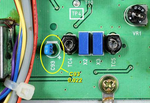 Capacitor C93 Top View |
||||||||||||||
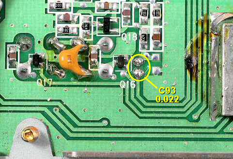 Capacitor C93 Bottom View |
||||||||||||||
| Procedure Locate C93 a 1uF 50Volt electrolytic capacitor and replace it with a 0.022uF (223) 50 Volt ceramic capacitor, see photo. |
||||||||||||||
| Noise Blanker Modification | ||||||||||||||
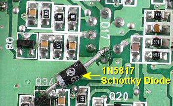 Fitting the Schottky Diode |
||||||||||||||
| Procedure Locate Q34 and solder a 1N5817 Schottky diode from its collector to ground, see photo. The anode of the diode should go to ground and the cathode (banded end) to the collector of Q34. The collector is the single pin on the side of the transistor facing the rear of the DX-394. |
||||||||||||||
| Back | ||||||||||||||