|
Mounting
The bhi DSP Module
The DSP module has four mounting holes that are used to retain the
unit inside the DX-394. Two holes need to be drilled in the front
panel for the keyboard. Hole sizes and positions can be found in the
bhi installation manual. The keyboard is retained using the supplied
(modified) ‘Z’ bracket and the keyboard holes in the front
panel are covered by a self adhesive label.
|
|
|
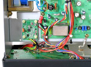
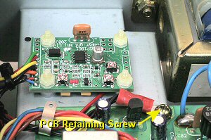
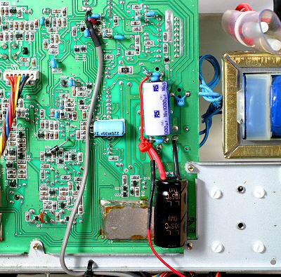
| Mount the DSP
module using four M2.5 nylon bolts, washers and nuts. |
The 0V
connection is formed using the M3 ring tag. A suitable 0V point is
the PCB retaining screw shown in the photo.
|
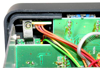
Modified Z Bracket and Keyboard Location
|
bhi DSP Keyboard |
|
| DX-394
Audio Amplifier Circuit Diagram |
|
|
| Parts
List |
| Component
Type |
Value |
Quantity |
| Resistor |
68R 0.6W |
1 |
| Resistor |
4.7k 0.6W |
2 |
| Resistor |
18k 0.6W |
1 |
| Ceramic Capacitor |
0.1uF (104) 50V |
3 |
| Ceramic Capacitor |
0.22uF (224) 50V |
3 |
| Electrolytic Capacitor |
470uF 16V |
1 |
| Electrolytic Capacitor |
1000uF 16V |
1 |
| DSP Module |
bhi NEDSP1061-KBD |
1 |
The resistors are Metal Film 1%
0.6W. Dimensions: 6.5mm x 2.5mm dia.
However, you can use 2% or 5% resistors at 0.5W or 0.25W.
|
| The small blue capacitors are
resin-dipped high quality multilayer plate ceramic. |
|
|
| Procedure |
Audio and Power Connections
|

bhi NEDSP1061-KBD Power Connection
|
Using a double layer of 'Quick Stick' pads mount a 1000uF 16 Volt
capacitor at the position shown in the photo. With its negative lead
to the negative connection of C157. From the positive side of C157
fit a 68 ohm 0.6W resistor to the positive lead of the 1000uF
capacitor. Place a 0.1uF (104) ceramic capacitor across the positive
and negative leads.
The 0.1uF (104) ceramic capacitor across C144 and C157 are fitted
during the power supply and audio amplifier modifications.
From the positive lead of the 1000uF capacitor connect the red
power wire to the bhi DSP module, see photo. |
|
| Procedure |
Modified PCB and Additional Components
|
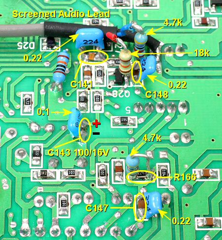
Place
a 4.7k 0.6W standard resistor across the 47k surface mount resistor
R166.
The 0.22uF (224) ceramic capacitors across C141, C147, C148 and the
0.1uF (104) ceramic capacitor across C143 are fitted during the
audio amplifier modifications. The value of C143 is also changed to
a 100uF at 16 Volt during these mods.
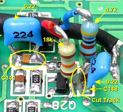
Mount vertically one end of a 4.7k resistor at C148, see photo.
Mount vertically one end of a 18k resistor to the collector of Q28,
see photo.
Cut the PCB track from the collector of Q28 to the ceramic
capacitor C148 at the position shown in the photo.
|
Screened Audio Connections
|
Fit
the screened audio lead:
- Red Audio Input via the 18k resistor
to the collector of Q28
- Blue Audio Output via the 4.7k
resistor to C148
- Black Audio Screen to 0V track on the
PCB
You must scrape away some of the green
solder-resist coating from the PCB to expose the copper track for
the audio screen ground connection.
bhi
DSP AM Noise Blanker Modifications |
|
| bhi
NEDSP1061 Adjustments |
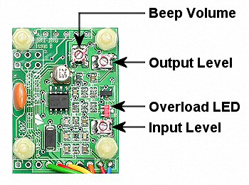
bhi NEDSP1061 Level Controls |
Adjust
the Output Level to its maximum position.
Adjust the Beep Volume to give the desired level, or off if
required.
Set the Input Level to the halfway position. The Overload LED
should not illuminate on loud signals. If it does back off the pot
slightly. |
|
| bhi
NEDSP1061 Operation |
All
functions of the NEDSP1061-KBD are controlled by a single button.
• Single press turns the noise cancellation on/off.
• Holding down the button changes the DSP filter level.
The mode of operation is indicated both visually and audibly. The
front panel LED is illuminated red when the noise cancellation is
off. When the noise cancellation level is changed the LED will flash
green to indicate which level has been selected. Simultaneously the
DSP will beep to give audible indication of DSP level. This allows
the operator to change the DSP level without having to look at the
LED to see which level has been selected. A short beep is emitted to
acknowledge a button press. The module will store the current DSP
level, and will return to this level when the equipment is switched
on. When the DX-394 is switch on the LED will illuminate red to
indicate the noise cancellation is off. The unit will flash/beep to
indicate the DSP filter level last used.
Full
bhi NEDSP1061-KBD Installation and Operating Manual pdf |
|